Alternative bottom beam reinforcement layouts can reduce congestion
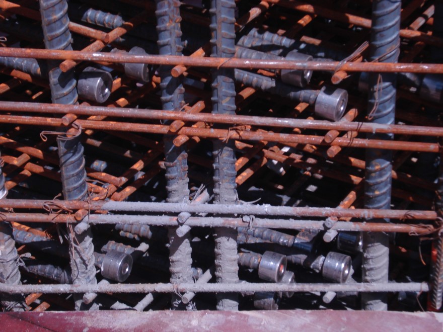
Beam-column joints are frequently areas of congestion in reinforced concrete construction. Several factors can contribute to beam-column joint congestion, such as column verticals that terminate in the beam with hooks and excessive top steel over the column. By far the most common problem, however, is the lapping of bottom beam bars at a column to meet the structural integrity requirements in Section 7.13 of ACI 318-05,[1] especially if the column and beam are the same width.
When the bottom beam bars are lapped at the column, the number of bottom bars that must pass through the joint doubles. The resulting congestion can contribute to poor consolidation of the concrete at a critical location where the concrete is under a complex state of stress and may also cause clearance problems with the column ties or beam stirrups. This congestion can be significantly reduced by using alternative splice locations and bar arrangements or by using mechanical couplers.
The following discussion presents several general splice arrangements, along with the advantages and disadvantages of each from a constructibility point of view. Designers must also consider structural issues when selecting among the alternative locations for the bottom bar splices. Only continuous bottom beam bars are shown. All other bars are omitted for clarity.
Arrangement #1 — Splices located at Supports
The most common arrangement is to locate all bottom bar splices at the supports as shown in Fig. 1, but this arrangement also produces the most congestion in the joint.
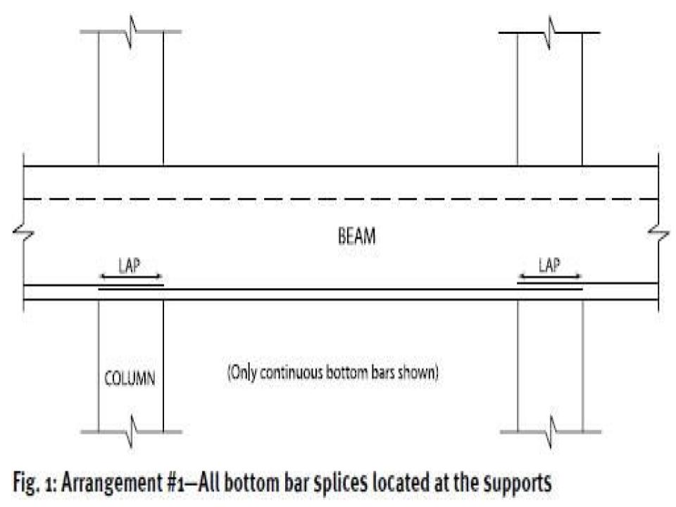
- Advantages:
Simplest to detail;
Good arrangement where beams are wider than the supporting columns; and
No additional steel is required. - Disadvantages:
Causes heavy congestion, especially if the column and beam are the same width or a large amount of reinforcement must be continuous;
Installation of single-bay preassembled beam cages is difficult; and
Installation of multiple-bay preassembled beam cages is almost impossible.
Arrangement #2 — 50% of Splices on Each Side of Supports
To ease congestion in the joints, half of the continuous bottom beam bars can be spliced on one side of the joint and the other half on the other side of the joint, as shown in Fig. 2. This arrangement eliminates half of the bars passing through the joint compared to Arrangement #1.
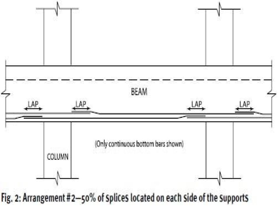
- Advantages:
With no splices over the supports, congestion is eased; and
No additional steel is required. - Disadvantages:
Detailing and preassembled cages are slightly more complex;
Preassembled beam cages are longer and more awkward to install; and
Installation of multiple-bay preassembled cages is very difficult.
Arrangement #3 — 100% of Splices Located on One Side of Supports
The third alternate arrangement is similar to Arrangement #2 except that all of the splices are located on one side of the joint, as shown in Fig. 3.
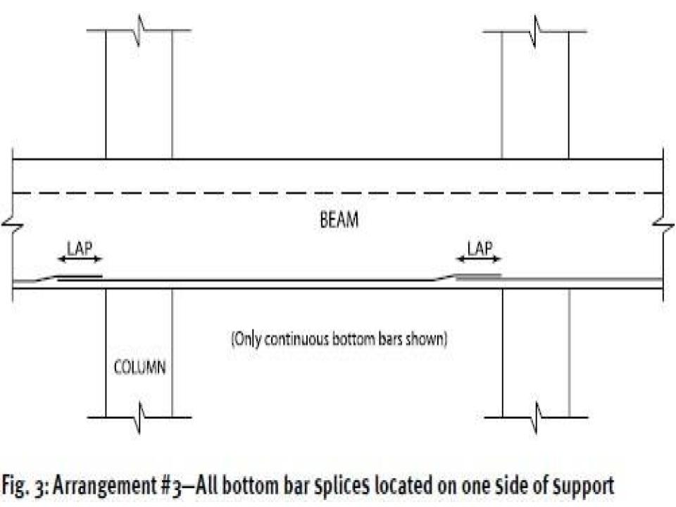
- Advantages:
Detailing and preassembled cages are relatively simple;
Preassembled cages are the same length as in Arrangement #1, but easier to install because they pass through only one joint; and
No additional steel is required. - Disadvantages:
Care must be taken to ensure that the cages are oriented correctly if installation begins at the center of the beam and progresses both ways.
Arrangement #4 — Splice Bars Added Through Supports
The fourth alternate arrangement is to add splice bars passing through the joint that are spliced to the bottom beam bars on both sides of the joint. This arrangement is shown in Fig. 4.
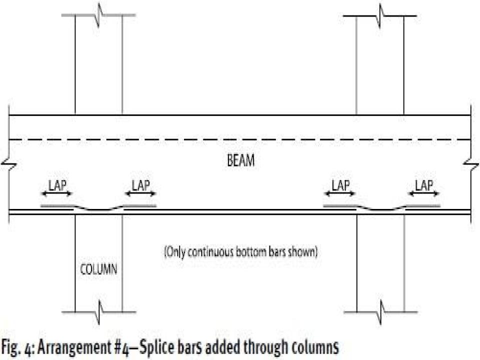
- Advantages:
No congestion at columns because splice bars through columns are added later;
Preassembled cages are shorter than any of the previous options;
Very easy to install preassembled cages because no bottom bars pass through the columns during installation; and
Best option for installation of multiple-bay preassembled cages. - Disadvantages:
Additional steel required.
Arrangement #5 — All bottom bars splice with type 2 Mechanical Couplers
Mechanical couplers provide a solution for alleviating congestion and improving structural integrity. Per ACI section 21.6 Type 2 mechanical couplers can be used at any location withing the structure including areas where inelastic yielding may occur. The arrangement is shown in Fig. 5.
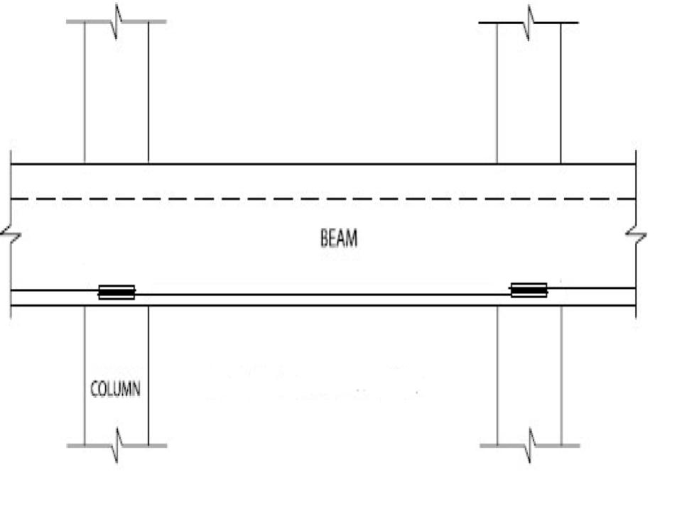
Fig. 5: Arrangement #5 – All bottom bars splices with Type 2 mechanical couplers
- Advantages:
No congestion at the columns
Material savings
Simple to install
Easy to install with preassembled cages - Disadvantages:
Requires preplanning as some systems require bar end threading
Design Considerations
Congestion should be considered when choosing the location of continuous bottom beam bar splices. Arrangements #2, #3, and #4 address this issue to varying extents.
Even though Arrangement #5 has a perceived added cost, the amount of steel and associated labor costs are reduced, it may be the most cost-effective in certain situations. The cost of any extra steel may be more than offset by the savings in labor or other costs. By permitting preassembly of the reinforcing steel cages on the ground, rather than "in the air," Arrangement #5 increases safety and eliminates the need for special scaffolding to support bundles of steel while the cages are being assembled in place.